Arduino Programming ଘʕ੭·͡ᴥ·ʔ ੭
- jiamin20
- Nov 30, 2021
- 4 min read
For this week of CPDD lesson, we were introduced to Arduino Programming. We were required to know how to set up an actual Arduino Maker Uno kit as well as learn how to use and create a circuit on Tinkercad which is a web-based simulation to develop and test Arduino code before we execute the code on the Arduino board.
Without further ado, let me share with you how I did mine!
TASKS:
1. Input devices:
a. Interface a Potentiometer Analog Input to maker UNO board and measure its signal in serial monitor Arduino IDE
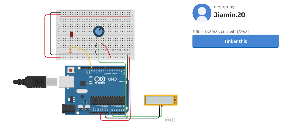
The Arduino's analog to digital converter, converts an incoming analog signal to between 0V and 5V into a range of numbers from 0-1023.
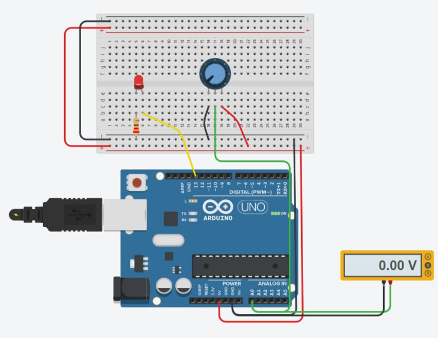
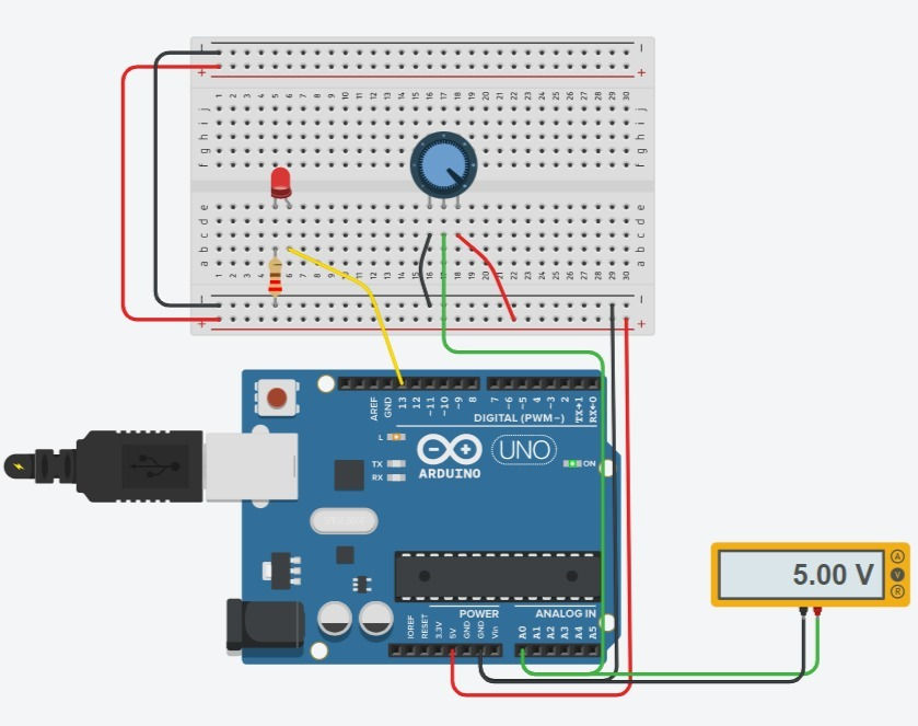
STEPS:
Set up the Arduino Uno R3 and the Breadboard (small).
Connect an LED to pin 13.
Add a resistor of 220 ohms.
Add a potentiometer to the basic LED circuit and wire it up the outer pins to power and ground, and the center pin to Arduino pin (A0).
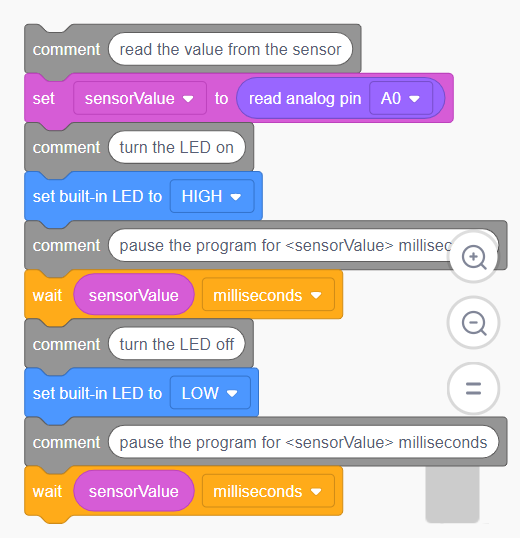
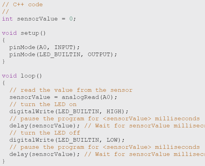
void loop (): the code inside the loop function runs over and over as long as the simulation is running.
pinMode (0, INPUT): to indicate that pin 0 is the input.
pinMode (13, OUTPUT): to indicate that pin 13 is the output.
analogRead: to listen to the pin A0 state, to read a signal
// function: comments added
delay (sensorValue): the values on the potentiometer changes as the knob of the potentiometer turns.
b. Interface a LDR to maker UNO board and measure its signal in serial monitor Arduino IDE

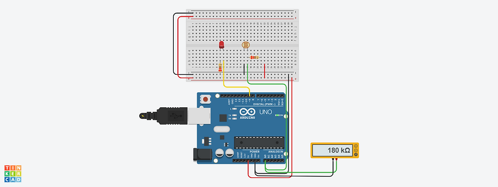
STEPS:
Set up the Arduino Uno R3 and the Breadboard (small).
Connect an LED to pin 13.
Add 2 resistors of 220 ohms.
Add a photoresistor.
Add a multimeter to the basic LED circuit. Connect the positive side to A0 and the negative side to ground.

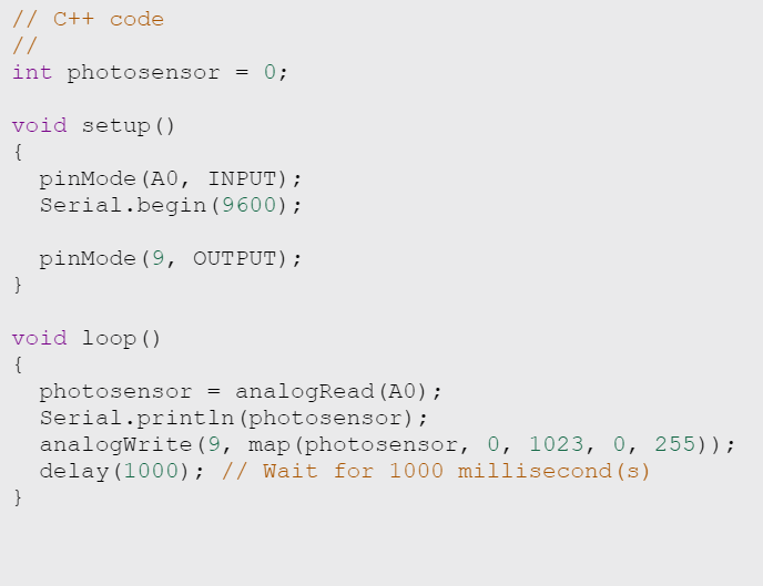
pinMode (A0, INPUT): to indicate A0 is the input.
pinMode (9, OUTPUT): to indicate pin 9 is the output.
Serial.begin(9600): establishes serial communication between Arduino board and another device. 9600 is the baud rate.
map (photosensor, 0, 1023, 0, 225 ): LEDs working range
analogRead (A0): LDR is connected to A0 on the Arduino board
Serial.println (photosensor): Prints data to the serial port
analogWrite(): Used to update status on pins, to output a signal
// function: comments added
delay(1000): there will be a delay or pause of 1 sec between this action.
For both (a) and (b) analog input was used. After performing the input tasks, I now know how the analog inputs work! In this example we use a variable resistor (a potentiometer or a photoresistor), we read its value using one analog input of an Arduino board and we change the blink rate of the built-in LED accordingly. The resistor's analog value is read as a voltage because this is how the analog inputs work.
2. Output devices:
a. Interface 3 LEDs (Red, Yellow, Green) to maker UNO board and program it to perform something (fade or flash etc)
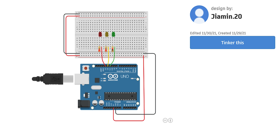
STEPS:
Attach wires to make an electrical connection. The LED (red) and resistor is connected in series with pin 13 and ground.
Add 2 more LEDs (green and yellow) and resistors and connect them to pin 12 and 11 respectively.
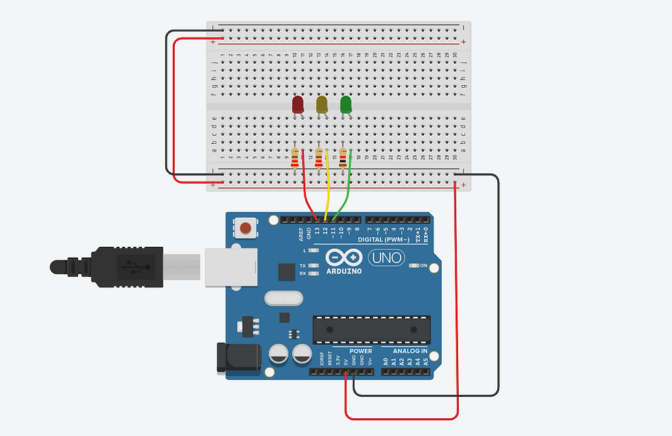
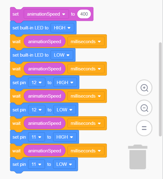
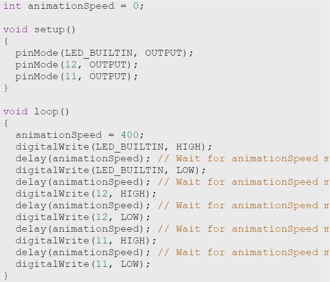
pinMode (): to indicate the outputs (pin 9,6,5) of the Arduino Uno, signals are being sent to an LED (pin 9,6,5)
for (brightness = 0; brightness <= 255; brightness += 5): brightness increases from 0 to 255 in increments of 5
for (brightness = 255; brightness <= 0; brightness += 5): brightness decreases from 255 to 0 in multiples of 5
analogWrite() function: to output a signal
// function: comments added
delay(30): there will be a delay or pause of 30 milliseconds between this action.
b. Interface the DC motor to maker UNO board and program it to on and off using push button on the boar
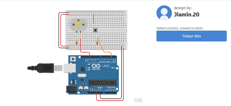
STEPS:
Add a DC motor and a push button on the breadboard
Add 2 resistors (220 ohms).
Connect the wires as shown below.
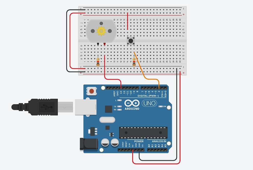
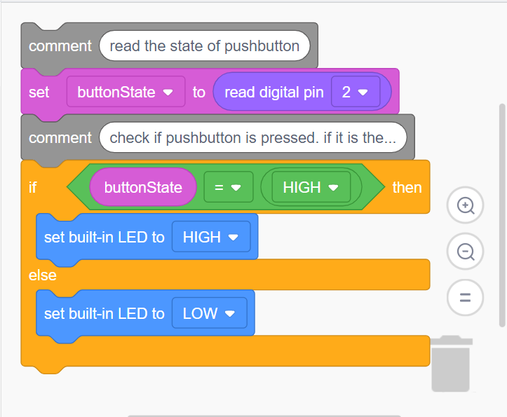
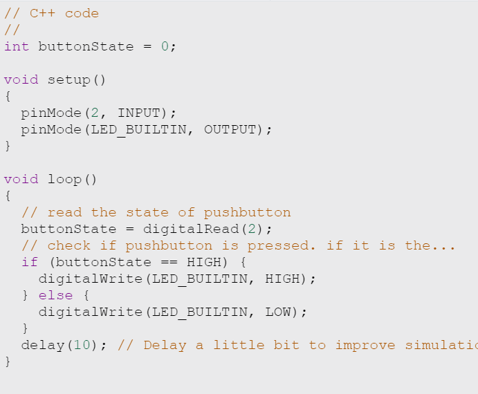
pinMode (2, INPUT): to indicate pin 2 is the input
pinMode (13, OUTPUT): to indicate pin 13 is the output
// function: comments added
delay(10): there will be a delay or pause of 10 milliseconds between this action.
buttonState = digitalRead(2): to listen to the pins state
if (buttonState == HIGH) {
digitalWrite (LED_BUILTIN, HIGH) ;
} else {
digitalWrite (LED_BUILTIN, LOW) ; : : evaluates a condition using comparison operators (<,>,== etc) if the requirements is met, the codes in the brackets are executed.
While interfacing an output device to Arduino board, I learnt that a processor is required for output devices. I also learnt how a processor worked! The processor is responsible for executing a sequence of stored instructions which is known as program. This program will take inputs from an input device, process the input in some way and output the results to an output device.
Problems faced (◎-◎;)
One of the problem faced when I performed the task was that I realised the wires connection are very important as it determines whether the device works or not. For my case, when I connect the multimeter, I connected the wires wrongly. The wires that was supposed to connect to 5V went to ground instead and vice versa. As a result, the multimeter did not show any voltage reading even when I adjusted the potentiometer. After I realised what went wrong, I went to change the wire connections and the multimeter worked!
Link to source codes: https://docs.google.com/document/d/1wuIr5LMo78pSlRxt6wHC4xGcb5kDYQ_a9AgHon7RGo0/edit?usp=sharing
REFLECTION TIME ٩(⊙‿⊙)۶
Through the tutorial sessions and practical sessions on Arduino programming, I realised how beneficial it is to learn how to program properly. When I first got my Arduino, I had no working knowledge of electronics or circuits. I thought Arduino programming was going to be really difficult but after trying it myself, it is not as difficult as I thought and was much easier than I expected.
I actually hoped that I would be able to remember what was taught and apply it in the future when I start on my capstone project. Since my group current idea was to build a UV light handphone sterilizer, we could use Arduino Uno to create a program for our sterilizer. For example, the input would be mass and the output would be UV light.
I can't wait to see how we are going to program our sterilizer using Arduino programming!
That's the end! Thanks for reading! ლ(◉❥◉ ლ)
Comments